-
Top page
>
-
Injection molding, page 04
Page 04 (Y2026)
Structural Analysis (Episode 33: Mesh Type)
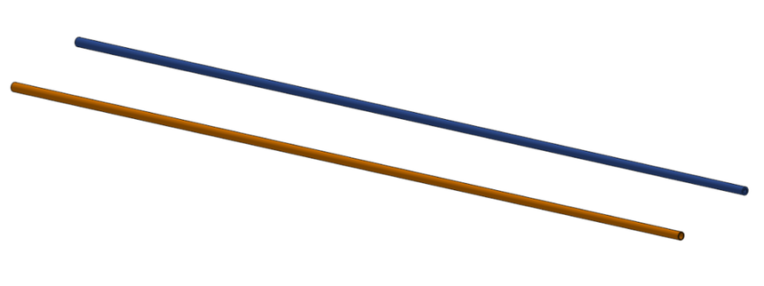
このセッションでは、解析結果に及ぼすメッシュタイプの影響を確認してみました。まず、中空のロッド状 (ゴルフクラブのシャフトのようなイメージしてください) の 3D モデルを 2 種類用意しました。長さ 600 mm で、元部分の外径が 6 mm から先端部にかけて外径が 4 mm に細くなるテーパー形状の物体です。肉厚は、均一に 1 mm のケースと元部分が 1 mm で、先端に行くにつれて 0.5 mm に徐々に細くなるケースを用意しました。
In this section, the effect of the mesh type on the analysis results was studied. First, two types of hollow-rod-shaped 3D-models (please imagine the shaft of a golf club) were prepared. They were 600 mm long and tapered, with an outer diameter of 6 mm at the bottom and 4 mm at the tip. There were two cases for the wall thickness: one with a uniform thickness of 1 mm and the other with a thickness of 1 mm at the bottom that gradually thinned to 0.5 mm at the tip.
これらのパートを、PrePoMax を使って "tetrahedral Gmsh" と "transfinite Mesh" でそれぞれメッシュ化して、形状非線形での静解析を行いました。元部に相当する面を完全拘束した上で、先端部に相当する面に 0.02 N の力を下向きに作用させました。ただし要素化にあたって、超有限要素を使ったケースではロッドの中心から半分に分割して要素化し、対称条件を付与しました。この場合の荷重条件は 0.01 N としました。なお材料は PerPomax のデータベースの中から 2014 Alloy (FM: 73,000 MPa, Poisson's ratio: 0.33) を選択して使用した。
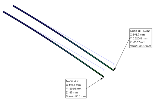
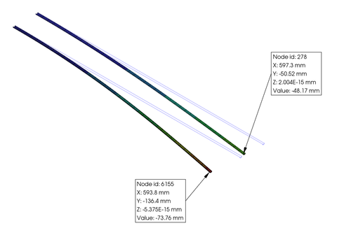
その結果として得られた荷重方向の変位等高線図を、下図に示します。左が "tetrahedral Gmsh"、右隣が "transfinite Mesh" です。
Using PrePoMax, these parts were meshed with "tetrahedral Gmsh" and "transfinite Mesh," then simulated using nonlinear geometrical static analysis. The surface corresponding to the base was fully constrained, and a downward force of 0.02 N was applied to the surface corresponding to the tip. However, when transfinite elements were used for meshing, the rod was divided in half at the center, and symmetry conditions were applied during meshing. In this case, the load condition was set to 0.01 N. The material used was 2014 Alloy (FM: 73,000 MPa, Poisson's ratio: 0.33) selected from the PerPomax database.
The resulting displacement contour plots in the load direction are shown below. The left plot is for “tetrahedral Gmsh,” and the right plot is for “transfinite Mesh.”
認識にくいと思われますので、一覧表として下に示します。Since it may be difficult to describe, I have provided a list below.
|
Part Thickness |
Number of Elements |
Max. Defflection |
Max. Stress |
CPU time |
| tetrahedral Gmsh |
Uniform |
44,502 |
33.6 mm |
50 MPa |
243.9 s |
| tetrahedral Gmsh |
Gradually thinned |
41,386 |
36.4 mm |
50 MPa |
as above |
| transfinite Mesh
| Uniform |
1,040 |
48.2 mm |
97 MPa |
46.6 s |
| transfinite Mesh |
Gradually thinned |
1,520 |
73.8 mm |
138 MPa |
as above |
以上の結果の違いは極端な例だとは思いますが、皆さんはどう思いますでしょうか? どちらのケースがより現実に近いと思うでしょうか? ご意見をお聞かせ願えないでしょうか。今回から各ページの最後に、皆さんがご意見や感想を書き込める簡易的なボードへのリンクを用意しました。まだ試験的な試みではありますが、忌憚のない投稿をお願いしたいと思います。
I understand that the differences in results above are extreme examples, but what do you think? Which case do you think is closer to reality? I would appreciate your opinion. Starting this time, I've added a link to a simple board at the end of each page where you can post your opinions and feedback. While this is still a trial initiative, I encourage you to share your candid thoughts.
Go back to the top of this page.