-
Top page
>
-
Injection molding, page 01
Page 01 (Y2023)
射出成形の初期条件設定のための考察 (Episode 1: Screw rotation speed)
熱可塑性樹脂の成形の中で、射出成形はもっとも一般的に広く用いられています。材料のペレットを加熱して溶かした液体状の樹脂を、低い温度の金型の中に注入して冷やし固める工法になりますが、その工程では適切な条件設定の入力が必要になります。しかし、射出成形を始めたばかりの技術者にとっては、「どういった条件が適しているか」の判断はなかなかつきにくいのではないかと思います。
そこで、ここでは条件を一つ一つ考察しながら、「金型が出来上がった後の一番最初の成形トライ時」に最初に設定されるべき条件を提案していきたいと考えています。そして、それらを一つにまとめたプログラムを作成したいと思っています。そんな試行錯誤の状況をこのサイトで扱っていきます。
Injection molding is the most widely used method of molding thermoplastic resins. It is a method of heating and melting material pellets and injecting the melt resin into a low temperature mold to cool and solidify, but this process requires input of appropriate condition settings. However, for engineers who have just started injection molding, I think it is difficult to judge "what kind of conditions are suitable".
Therefore, here, I'd like to consider the conditions one by one and propose the conditions that should be set first at beginning of the first molding trial when the mold is completed. And I would also like to create a software program that combines them into one. This site will deal with such a trial and error situation.
プログラム化にあたっては python を使っていきたいのですが、始めたばかりの私にとっては分からない事だらけ。ですので詳しい方がいらっしゃれば、アドバイス頂けたら嬉しいです。
I will use python for programming, but there are many things I do not understand as I am just starting to learn. So if anyone has more information, I would appreciate it if you could give me some advice.
まず手始めにスクリューの回転数から考えましょう。ホッパーからシリンダー内に供給されたペレットは、スクリューが回転するとシリンダーからの熱を受けながら前方に移動し、圧縮ゾーンに達すると圧縮・混錬されて溶けていきます。このとき、スクリューが回転しながら樹脂にせん断力を加えるため、その回転速度は可塑化に大きく影響します。
Let's start with screw rotation speed. Pellets supplied from the hopper into the cylinder move forward while receiving heat from the cylinder as the screw rotates, and when they reach the compression zone, they are compressed, kneaded and melted. At this time, as the screw rotates, it applies a shearing force to the resin, so the rotation speed greatly affects plasticization.
ところが・・・、スクリュー回転速度の設定は、ほとんどの成形機が
rpm、即ち一分間あたりの回転数で設定するようになっています。この場合、スクリュー直径の異なる成形機では外周部の速度が異なってしまうため、同じ回転数を与えても樹脂に与える影響度合いが異なってしまいます。即ち、スクリュー回転が溶融樹脂に及ぼす影響を想定するためには、スクリュー外周速度を考慮に入れる必要があります。
However, most molding machines set the screw rotation speed in "rpm", that is, rotation number per minute. In this case, molding machines with different screw diameters will have different peripheral speeds, so even if the same number of revolutions is given, the effect on the resin will be different. In other words, in order to estimate the effect of screw rotation on the melt resin, it is necessary to take into account the peripheral speed of the screw.
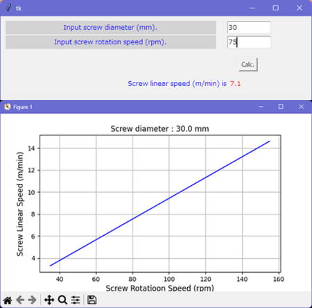
そこで今回は、スクリューの外径と回転数から、スクリュー外周速度を算出てしみたいと思います。計算自体は簡単で、単純に (外周長) x (回転速度) ですが、これを python を使ってプログラムを作って計算させたいと思います。ライブラリに tkinter を使って入力項目を表示させて入力を促し、入力を終えると、算出した外周速度を表示した後に、入力した回転数の前後を matplotlib ライブラリを使ってグラフ化するプログラムを書いてみました。これを実行すると左の図のような結果が出力されます。この時、グラフを表示させるためには tkinter 画面を " X " ボタンを押してウインドウをクローズしなければなりません。これだと、せっかく計算した値がグラフの出現と同時に消えてしまいます。これを修正していくためには、もっといろいろな構文を覚えないといけないようです。
Therefore, this time, I'd like to calculate the screw peripheral speed from the screw outer diameter and rotation speed. The calculation itself is simple, simply (Perimeter Length) x (Rotational Speed), but I wanna create a program using "python" to calculate it. Use "tkinter" to display the input items in the library and prompt for input, and when the inputs were completed, after displaying the calculated peripheral speed, wrote a program to graph the input rotation speed using "matplotlib" library. Running this will output the result shown in the figure on the left. At this time, in order to display the graph, "tkinter" screen must be closed by pressing the "X" button. With this, the calculated value disappears at the same time as the graph appears. In order to fix this, it seems that I have to learn more syntax.
射出成形の初期条件設定のための考察 (Episode 2: Optimum value of screw rotation speed)
前回のトピックでスクリューの外周速度について触れましたが、重要なのは、どのくらいの速度が適切なのかということになると思います。ですが、これに関しては様々な情報を収集して考慮に入れないとなりませんので、初期条件の入力段階では絞ることが出来ないと思います。
大まかにですが、 5 ~ 10 m/min. 程度の値からスタートすることをお勧めします。オレフィン系樹脂などではもう少し早くても OK な場合もあるでしょうし、熱にセンシティブなエンプラなどでは逆にもう少し遅くする必要があるかもしれません。上記の値からスタートして、使用樹脂のせん断発熱による影響度合いの大きさや、溶融樹脂の滞留時間 (= シリンダー容量と 1
ショットの容量と 1 サイクル時間によって決まります) 等によって調整方向を決めていきます。さらに最適条件の検討としては、成形品の出来栄えである外観や色、物性等が十分に安定した品質となる方向に模索していくことになります。この際には、同一条件で連続成形を行った時の可塑化時間の安定性 (バラツキの小ささ) にも着目すると良いと思います。また、あまりに速度が遅く、可塑化時間が冷却時間を超えてしまうとコストにも影響してしまいますから、この点で考慮に入れる必要がありますね。
I touched on the peripheral speed of the screw in the previous topic, but I think the important thing is what speed is appropriate. However, since various information must be collected and taken into account regarding this, I don't think it can be narrowed down at the initial condition input stage.
As a rule of thumb, I recommend starting with a value of around 5-10 m/min. For olefin resins, it may be OK even if it is a little faster, but for heat-sensitive engineering plastics, it may be necessary to slow it down a little. Starting from the above values, the direction of adjustment is determined according to the degree of influence of shear heat generation of the resin used, the residence time of the melt resin (= Determined by cylinder capacity, 1 shot volume and 1 cycle time), etc. Furthermore, as for the examination of the optimum conditions, you will search for a direction in which the appearance, color, physical properties, etc., of the molded part are sufficiently stable. In this case, I think it is good to pay attention to the stability of the plasticizing time (small variation) when continuous molding is performed under the same conditions. Also, if the speed is too slow and the dosage time exceeds the cooling time, it will affect the cost, so this point needs to be taken into consideration.
射出成形の初期条件設定のための考察 (Episode 3: Shot size)
さて、次に計量値の設定について考察してみたいと思います。基本的には 1 ショットの容積をスクリューで計量すれば良いのですが、通常はある程度のクッションをとります。つまり、射出が終わった時点でスクリューが前進限まで移動するのではなく、前進限から +5 mm 程度の余裕をとって成形品にしっかりと圧力をかけてあげる必要があります。スクリューが前進限に達してしまうと、それ以上の圧力を成形品にかけることが出来なくなり、ショートショットや寸法不良などの原因になるのを防ぐ事が目的です。また、ショット間のばらつきを配慮する目的もあります。
Next, I would like to consider setting the shot size. Basically, it is enough to measure the volume of one shot with a screw, but usually a certain amount of cushion is taken. In other words, instead of moving the screw to its forward limit when injection is finished, it is necessary to keep a margin of about +5 mm from the forward limit and apply firm pressure to the molded part. The purpose of this is to prevent short shots and dimensional defects from occurring when the screw reaches its forward limit and no further pressure can be applied to the molded product. It also serves the purpose of accounting for shot-to-shot variability.
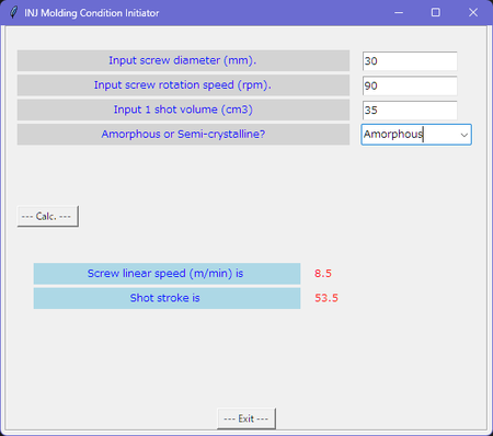
また、初期条件においては金型の破損や離型不良を防止するため、僅かにショートショットになるぐらいの計量値からスタートする方が安全です。このため、ここではあらかじめ算出された 1 ショットの容積と同等の容量を計量することにします。この時、常温で固体の成形品と溶融温度で液体の樹脂では比容積が異なりますので、これを配慮する必要がありますが、正確な算出には P (圧力) - V (比容積) - T(温度) データが必要になります。しかしながら、こういったデータはなかなか入所できにくいですね。しかし、ここでは初期条件の設定が目的なので、そこまで正確ではなくても非晶性樹脂と結晶性樹脂とに分けて、大まかな値を計算することにします。その上で、V/P 切り替え位置を 2 mm 程度取りつつ、保圧を 30 MPa 程度の低い値を設定するることで、可充填を防ぐこととします。
In addition, it is safer to start with a calculated screw stroke that is slightly short shot in order to prevent mold damage and mold release issue in the initial conditions. For this reason, I will use a volume equivalent to the pre-calculated volume of one shot. At this time, the specific volume of the molded product, which is solid at room temperature, differs from that of resin, P (Pressure) - V (Volume) - T (Temperature) data should be required to calculate its accurate value. However, since the purpose here is to set the initial conditions, even if it is not so accurate, I will divide it into amorphous resin and crystalline resin, and calculate rough values. On top of that, I will set the holding pressure to a low value of about 30 MPa while keeping the V/P switching position about 2 mm to prevent excessive filling.
これらの前提をもとにプログラムを組んでみました。(右図)
I made a python program based on these assumptions. (Right figure)
射出成形の初期条件設定のための考察 (Episode 4: Cylinder and tool temperature setting)
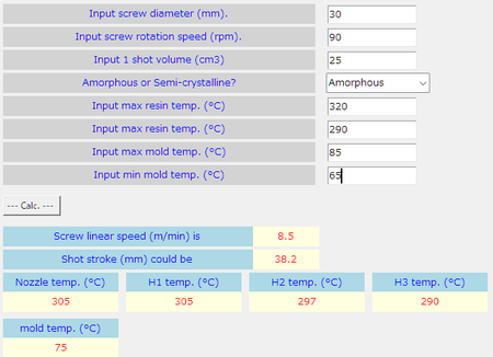
シリンダーの温度設定と金型温度については、お使いになる材料の材料メーカーが推奨する温度の範囲内で初期条件を設定するのが、良い方法と思います。樹脂温度と金型温度はは推奨範囲の中心値を設定します。この時、シリンダー温度は最前部の設定をその値として、一番後部を推奨範囲の一番低い値に設定します。その間の部分は最前部から最後部に向かって下げていく設定として、ノズル部分はシリンダー最前部と同じ設定にします。また、金型温度は温調器の設定温度ではなく、金型表面の温度を実測して値を調整します。
Regarding the cylinder temperature and mold temperature, I think it is a good idea to use the initial conditions within the temperature range recommended by the material manufacturer for the material you are using. Set the center value of the recommended range for the resin and mold temperature. At this time, the front zone temperature is set to above value, and the rear zone setting is set to the lowest value in the recommended range. The part in between them set to go down from the front zone to the rear zone, and the nozzle is set to the same setting as the front zone of the cylinder. Also, the mold temperature is adjusted by actually measuring the temperature of the mold surface, not by the set temperature of the temperature controller.
そして成形を開始した後に、充填状況を見てさらに温度を調整する必要があります。ただし、事前に成形加工解析によってシミュレーションがなされているのであれば、その設定を用いてもいいでしょう。尚、ノズル部の設定温度は、金型と接して成形した時のスプルー内でのつまり具合や、スプルーからの鼻たれや糸引きの状態を見て調整します。シリンダー後部への温度勾配については、計量時間のバラツキやペレットのスクリュー前方への移送具合いを見て判断します。移送がうまくいかない時はホッパー下の温度が上手くコントロールされているかもチェックしてみて下さい。さらに、熱にセンシティブな樹脂の場合はシリンダー容量と 1 ショットの容量がマッチしているかに留意した上で、滞留時間が長くなってしまう場合は温度勾配を調整する必要もあるかもしれません。
And after starting molding, it is necessary to check the filling situation and further adjust the temperature. However, if a process simulation has been performed in advance, that setting may be used. In addition, the set temperature of the nozzle part is adjusted by looking at the condition of clogging inside the sprue when it is molded in contact with the mold, and the state of drolling and stringiness from the sprue. The temperature gradient to the rear of the cylinder is judged by looking at the variation in dosage time and how pellets are transferred to the front of the screw. If the transfer is not going well, check if the temperature under the hopper is well controlled. Additionally, for heat-sensitive resins, it may be necessary to match the cylinder volume to the one-shot volume, and adjust the temperature gradient if the residence time increases.
射出成形の初期条件設定のための考察 (Episode 5: Injection speed)
次は射出速度についてです。最終的には外観上の問題や充填性など、いろいろな点を考慮に入れて調整することになりますが、これからトライを始める時の初期設定としては、次のように考えて設定してみると良いのではないでしょうか。
Next is the injection speed. Ultimately, you may have to make adjustments taking various points into consideration, such as problems with appearance and filling ability.
まずはノズル直径からその部分のせん断速度を算出します。ただし、ここでは計算を簡単にするために溶融樹脂をニュートン流体とみなして便宜的に計算します。得られた値はあまり意味を持ちませんが、その値がある一定値となるように射出速度を求めて、これを初期設定値とします。 これによって成形トライのスタート時点での充填速度を一定の条件をもとに算出した初期値とすることが出来ます。そしてその後は、成形品の出来栄えを見ながら調整していくことになります。
First, calculate the shear rate at nozzle from its diameter. However, in order to simplify the calculation, the molten resin is assumed to be a Newtonian fluid and calculated for convenience. The obtained value does not have much meaning, but the injection speed is obtained so that the value becomes a certain value, and this is used as the initial setting value. This makes it possible to set the filling (injection) speed at the start of the molding trial as the initial value calculated based on certain conditions. After that, you will make adjustments while looking at the quality of the molded parts.
射出速度は成形品の、特に外観について、大きく影響します。場合によって多段の速度切り替えが必要になってきますが、その場合は、切り替え位置が本当に適正かどうかを常に気にかけながら変更するようにしてください。そのためにはスクリューの動きを常に監視して、成形機に表示されるスクリュー位置や速度のプロットを確認するようにしましょう。
Injection speed has a great influence on the appearance of the molded part. Depending on the situation, you may need to switch speeds in multiple stages. In that case, always make sure that the switching location is really appropriate. To do this, always monitor the movement of the screw and check the screw position and speed plots displayed on the molding machine.
ここまで、成形トライ時の初期設定条件を考察して、それを算出するソフトを python で作ってきましたが、ここまでの段階で 256 行も費やしています。コメントとかも含めてではあるのですが、それにしてもこんなに長くなるなんて・・・。大変なものですねぇ。初心者でもあるがゆえに未熟ですので、まだ短く出来る余地はあるとは思いますが、完成度もまだ上げないといけないことを思うと、それほど変わらないかもです。これに関してはもう少し修業しないと。
So far, I have considered the initial setting conditions at the time of molding trials and created software in python to calculate them, but I have spent 256 lines already. I'm including comment lines, but even so, it was going to be this long... It's a big deal. I'm still a beginner, so I'm immature, so I think there's still room to shorten it, but considering that I still have to improve the degree of perfection, I don't think it will change much. I need to study a little more about this.
射出成形の初期条件設定のための考察 (Episode 6: XY plot visualization)
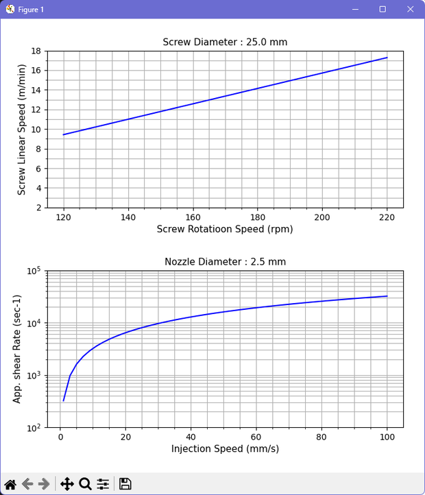
python を走らせると、前述のアウトプットと同時に、スクリューの回転速度と、溶融樹脂をニュートン流体と仮定して簡易的に算出した「ノズル部における見かけのせん断速度」をグラフ化できるようにしてあります。二つのグラフが描かれますが、上段がスクリュー速度、下段がノズル部でのせん断速度です。これらを見ながら、現在の条件がどのような位置づけとなっているかを想像しながら条件調整していくと良いと思います。
When python is run, the rotation speed of the screw and the "apparent shear rate at the nozzle", which is simply calculated assuming that the melt resin is a Newtonian fluid, are graphed at the same time as the above outputs. Two graphs are drawn, the upper one is the screw speed and the lower one is the shear rate at the nozzle. While looking at these, I think it would be good to adjust the conditions while imagining what the current conditions are positioned.
ちなみにですが、成形条件を設定する際、せん断速度で一番注目すべきはゲート部になります。ここでは流路が絞られており、最もせん断速度は高くなりやすいです。しかし、その正確な計算は複雑ですので、その計算をしたい場合は専用のシミュレーション・ソフトを利用してください。ここではあくまで初回トライにおける初期条件設定を求めることを大前提としています。
By the way, when setting the molding conditions, the gate section should be the most important in terms of shear rate. The flow path is narrowed here, and the shear rate tends to be the highest. However, the exact calculation is complicated, so if you want to do the calculation, please use dedicated simulation software. Here, the major premise is to find the initial condition settings for the first trial.
これでようやく主な条件設定を取り上げて、初期設定を提案することが出来ました。残りの条件に付いては、例えば冷却時間は考慮すべき要因が多すぎるために、なかなかここでは取り上げられません。思い切って例えば、一律 20 秒 (からスタート) とかしたほうが良いかも分かれませんが、もう少し考えてみたいと思います。
まずはこれでひと段落とします。python コードについては、エラートラップなどを含めてもう少し精査しします。
Now we can finally address the main conditional settings and propose initial settings. The remaining conditions, for example cooling time, are not easily covered here because there are too many factors to consider. I don't know if it's better to take the plunge and set it to 20 seconds (start from), for example, but I'd like to think about it a little more.
Let's take a break with this first. I'll look into the python code a bit more, including error trapping and such.
こちらのサイトにつきまして、ご意見、ご希望などありましたら、"about me" のページにありますリンクからメールが出来ますので、宜しくお願いします。
If you have any comments or requests regarding this site, please send me an email using the link on the "about me" page.
射出成形の初期条件設定のための考察 (Episode 7: Tried using the software)
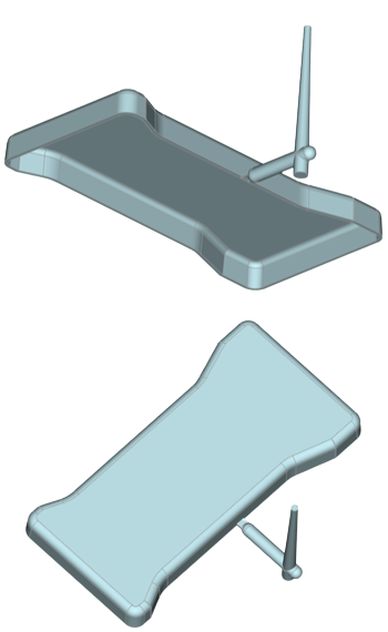
さて、ひとまず完成したプログラムを走らせてみた例をご紹介します。その前に簡単な製品の形状を 3D-CAD で作ってみました。作成にあたっては FreeCAD というオープン・ソース・ソフトウエアを使いました。これまでは SOLIDWORKS を使用してたのですが、FreeCAD での作成は初めてでしたので、単純形状の作成といえどもとても時がかかってしまいました。SOLIDWORKS なら 20 分程度で出来るものが、一週間以上もかかってしまいました。慣れれば短縮できるとは思いますが、なんだか痒いところに手が届かない感じはします。右図にその形状を示します。
1 shot の体積を計算すると、62.7 cm3 でした。また、成形品の投影面積から所要型締力を算出すると、120 ton の型締力が適切と思われます。そこで、住友重機械工業株式会社様のウエブサイトからそのくらいの型締力の機会を探してみると、SE-130EV-A という機種がありました。その中から C360M の 32 mm 径のスクリューで見てみると、理論射出体積が 129 cm3 であり、スクリューストロークが 160 mm とありました。これらの情報を元に python プログラムを走らせてみました。
Now, let me introduce an example of running the completed my program. Before that, I made a simple part shape with 3D-CAD. I used an open source software called FreeCAD to create the shape. I used to use SOLIDWORKS before, but it was my first time using FreeCAD, so even creating a simple shape took a lot of time.The work took over a week what I spent just 20 minute if I use SOLIDWORKS. I think it can be shortened if I get used to it, but I feel like I can't reach the itchy place. The figure on the right shows its shape.
When I calculated the volume of one shot, it was 62.7 cm3. Also, when calculating the required clamping force from the projected area of the molded product, 120 ton seems appropriate. Therefore when I searched the website of Sumitomo Heavy Industries Co., Ltd. for an opportunity with that level of clamping force, I found a model called SE-130EV-A. Among them, when I selected C360M and 32 mm screw diameter, it has 129 cm3 of a theoretical injection volume and 160 mm of a screw stroke. I ran thr python program based on these information.
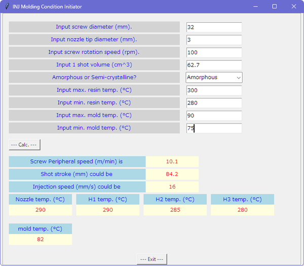
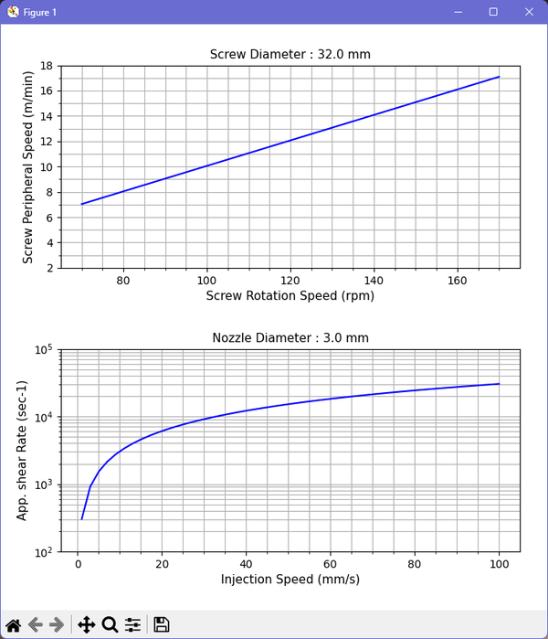
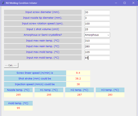
スクリュ回転については、とりあえず 100 rpm を入力しました。また、ノズル径については情報がありませんでしたので、 3 mm を入力ました。右図はその入・出力のスクリーンショットです。また、グラフアウトプットも示します。スクリュー外周速度は 10.1 m/min と出ていますので、もう少し遅くてももいいかもしれません。8 m/min を目指しして 80 rpm としてもいいでしょう。
さて、以上が今回制作してみた python を使用した、射出成形の初回トライ時の初期条件設定用のソフトの使用例になります。上記では使用樹脂は例として適当に非晶性樹脂として溶融温度と金型温度を適当に入力しましたが、いかがでしたしょうか? これらのアウトプットの他に、保圧を 30 MPa、保圧時間 1 s、サックバックを 1 mm 程度に設定すればいいでしょう。
For the screw rotation, I entered 100 rpm for the time being. Also, there was no information about the nozzle diameter, so I entered 3 mm. The figure on the right is a screenshot of its input/output. It also shows the graph output. The screw peripheral speed is 10.1 m/min, so it may be a little slower. If you'd like to aim 8 m/min, 80 rpm would be fine.
Well, above is the software using example for setting the initial conditions at the first trial of injection molding using python that I created this time. In the above example, the resin used was an amorphous resin, and the melting temperature and mold temperature were entered appropriately. Plus, you can set 30 MPa as holding pressure 1 s for the time.then set 1 mm as suck back.
以上をまとめると、今回の入力値から得られた初期設定条件は、
シリンダーノズル部の温度設定 : 290°C
シリンダー前部の温度設定 : 290°C
シリンダー中部の温度設定 : 285°C
シリンダー後部の温度設定 : 280°C
金型温度 : 82°C
スクリュー回転数 : 80 rpm
射出速度 : 16 mm/s
保圧 : 30 MPa
保圧時間 : 1 s
冷却時間 : 20 s
計量値 : 84.2 mm
サックバック : 1 mm
To summarize the above, the initial setting conditions obtained from the input values this time are:
Cylinder nozzle temperature : 290°C
Cylinder front temperature : 290°C
Cylinder middle temperature : 285°C
Cylinder rear temperature : 280°C
Mold temperature : 82°C
Screw rotation speed: 80 rpm
Injection speed: 16 mm/s
Holding pressure: 30 MPa
Hold time: 1 s
Cooling time: 20 s
Shot stroke: 84.2 mm
Suck back: 1 mm
ご質問等ありましたら、"about me" のページの一番下のリンクからメールを頂けたら幸いです。
If you have any questions, please send me an email from the link at the bottom of the "about me" page.
射出成形材料の溶融粘度 (Episode 8: Material melt viscosity )
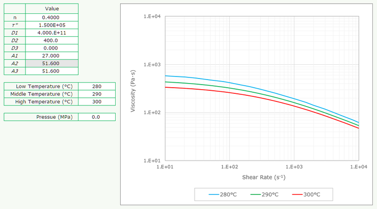
ここでは、材料の溶融粘度について触れてみたいと思います。プラスチックの溶融時の粘度は、温度やせん断速度によって変化します。これを測定するにはキャピラリー・レオメーターがよく使われます。これは、ピストンを使って、溶融樹脂が細い管から押し出される時のピストンの速度と反力を計測して、みかけの粘度を算出します。したがって、アウトプットは測定点のみとなりますが、成形加工のシミュレーションに使用するためにはこれでは不足で、想定されるすべての領域での粘度データが必要になります。これに対応するため、測定で得られた測定点から回帰 (フィッティング) を行います。この時によく用いられるのが、Cross-WLF 式になります。
右図は、この Cross-WLF 式を使ってせん断速度と粘度を3つの温度で、エクセルを使ってグラフ化したものになります。Cross-WLF 式では、図のように 8 つの値が用いられます。ただし、ここでは任意の値を入力しています。
Here, I would like to touch on the melt viscosity of materials. The viscosity of plastics when melted changes with temperature and shear rate. A capillary rheometer is often used to measure this. This uses a piston to measure the speed and reaction force as it pushes the melt resin out of capillary, and calculates the apparent viscosity. Therefore, the outputs are only the measurement points, but this is insufficient for use in molding process simulations, and viscosity data in all possible regions is required. To deal with this, regression (fitting) is performed from the measurement points obtained. Cross-WLF formula is often used in this case.
The figure on the right is a graph of shear rate and viscosity at three temperatures using this Cross-WLF equation, using Excel. It uses eight constants, as shown. However, here I entered arbitrary values.
図から、樹脂の溶融粘度はせん断速度が高くなると低下することが分かります。その傾向は比例的でなく、せん断速度が高いほど強くなります。これが溶融樹脂の特徴であり (非ニュートン流体)、水のような液体と異なる点になります。そしてこれは射出速度を速くすることによって粘度が下がり、充填性が向上する可能性を示唆します。その反面、焼けや肉厚差によってフローパターンが変化して充填不足になる原因になったりもしますから、注意が必要です。
The figure shows that the melt viscosity of the resin decreases as the shear rate increases. The tendency is not proportional and becomes stronger at higher shear rates. This is a characteristic of molten plastic (non-Newtonian fluid) and makes it different from liquids such as water. And this suggests that increasing the injection speed may lower the viscosity and improve flowability. On the other hand, care must be taken as it may cause to burning defect, or unexpected resin flow which it is due to differences in wall thickness.
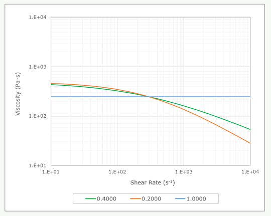
ちなみに、Cross-WLF 定数のうち n はべき乗指数を表し、この値が小さくなると直線部の勾配が増します。右図は n の値を 0.4, 0.2, 1.0 と変えてグラフを描きました。n が 0.2 の時は 0.4 のときと比べて傾きがきつくなることが分かります。また、1.0 の時は傾きがなくなり、せん断速度の影響が見られなくなります。このような液体はニュートン流体と呼ばれます。
By the way, constant n in the Cross-WLF formula represents the power exponent, and as this value decreases, the slope of the straight line increases. The graph on the right was drawn by changing the value of n to 0.4, 0.2, and 1.0. It can be seen that when n is 0.2, the slope is steeper than when n is 0.4. Also, when it is 1.0, there is no slope and the effect of shear rate is no longer visible. Such liquids are called Newtonian fluids.
射出成形材料の状態図 (Episode 9: P-V-T )
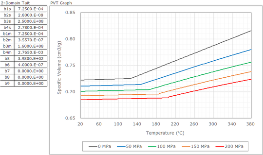
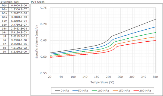
右に示すのは、熱可塑性プラスチックの P (圧力) - V (比容積) - T (温度) の状態を表したグラフになります。こちらも、全ての条件における情報が必要なため、CAE 解析においては測定結果をフィッティングして用いられます。この時、多く用いられているのが 2 領域の Tait 式です。図の左側には、各パラーメーターが表示されていますが、これらの値は私が適当に入力しましたので、特定の材料のものではありません。上側が非晶性材料であり、下側が結晶性材料の特徴を表現しています。圧力毎の比容積の値を、温度を横軸として、各パラメーターの値からエクセルでグラフ化しています。
Shown right are graphs showing the P (pressure) - V (specific volume) - T (temperature) state of thermo plastic. These also require information under all conditions, so they are used by fitting the measurement results in CAE analysis. At this time, the two-domain Tait equation is often used. On the left side of the diagram, each parameters are displayed, but these values are not for specific materials because I entered them into ata arbitrarily. The upper side shows the characteristic of amorphous material, and the lower side shows semi-crystalline material. The specific volume values for each pressure are graphed in Excel using the values of each parameter, with temperature as the horizontal axis.
非晶性材料 (上側) のグラフを見ると、比容積の値がある温度の前後でその傾きが変化している事が分かります。それがガラス転移点と呼ばれる温度になります。ガラス転移点を挟んでそれより高いもしくは低い温度の領域で、ほぼ一定のの勾配を持った直線で比容積が表されています。また、ガラス転移点は圧力が上がると高い温度にシフトすることも分かります。
これに対して結晶性材料では、ある温度の点から低い時に、比容積が急激に低下する様子が観察されます。これが結晶化による体積収縮を示します。これが結晶性樹脂の特徴になります。そしてこのことが成形収縮が大きくなる一因となっています。
ところで Tait 式のパラメーターを見ると、b7 ~ b9 の値に数字が入っています。非晶性材料ではこれらの値はすべて 0 でした。この部分がグラフ上で体積が急激に低下している部分を表します。
Looking at the graph for the amorphous material (upper side), you can see that the slope of the specific volume value changes before and after a certain temperature. It is the temperature is called the glass transition temperature. The specific volume is expressed as a straight line with an almost constant slope in the temperature range above or below the glass transition point. It can also be seen that the glass transition temperature shifts to higher temperatures as pressure increases.
On the other hand, in semi-crystalline materials, the specific volume is observed to decrease rapidly as the temperature decreases from a certain temperature. This indicates volumetric shrinkage due to crystallization. This is a characteristic of semi-crystalline resin. This is one of the reasons why mold shrinkage increases.
By the way, if you look at the parameters of the Tait formula, the values b7 to b9 contain numbers. All these values were 0 for amorphous materials. This part represents the part on the graph where the volume is rapidly decreasing.
冷却時間 その 1 (Episode 10: Cooling time, #1)
ここで冷却時間について触れてみたいと思います。熱可塑性樹脂の成形ですから、成形品を突き出す時に樹脂が十分な硬さになっていることが必要なので、まず一次元非定常熱伝導式を用いて樹脂の内部温度の推移を求めてみます。前提としては、樹脂の最表面、すなわち金型と触れている最表層が、金型温度を保ち続けて一定であるとします。実際の成形では、金型表面は溶融樹脂が流れてきたときには、その熱の影響受けて一時的に温度が上がります。そして時間が経つにつれて熱移動が行われて温度低下していきます。ここが実際とは異なる点になりますので、ですから、ここで求める時間は、あくまで最も理想的なものとして扱う必要があります。
I'd like to touch on cooling time here. Since we are molding thermoplastic resin, it is necessary that the resin is sufficiently hard when ejecting the molded product, so first let's use a 1D unsteady heat conduction equation to find the change in the internal temperature of the resin. The premise is that the outermost surface of the resin, that is, the outermost layer that is in contact with the mold, continues to maintain a constant temperature which it is the same value as tool temperature. During actual molding, when melt resin flows through the mold surface, the temperature temporarily rises due to the heat by melt resin. As time passes, heat transfer occurs and the temperature decreases. This is where things differ from reality. Therefore, the time required here should be treated as the most ideal.
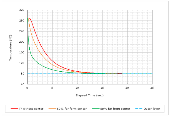
上の図は横軸に時間を、縦軸に温度をとって、経過時間とともにある温度に触れた溶融樹脂の温度が推移していく様子をプロットしたものです。入力項目は初期の溶融樹脂温度、金型温度、成形品の肉厚、樹脂の熱伝導率、および比熱になります。出力は温度ですが、赤実線は肉厚中心、オレンジが肉厚中心から 50% 外側の点、緑の実線は肉厚中心から 80% 外側の点、そして水色の破線は最表層の温度を示し、ここは金型温度と同じ温度で終始一定となります。今回の例として、樹脂温度は290°C、金型温度は 80°C、熱伝導率は 0.2 W/m-K、比熱は 1200 J/kg-K、肉厚は 2 mm を入力しました。
次のエピソードに続く。
The figure on the upper plots time on the horizontal axis and temperature on the vertical axis, and shows how the temperature of melt resin that touches a certain temperature changes over time. The input items are the initial melt resin temperature, mold temperature, molded product wall thickness, thermal conductivity of the resin, and specific heat. The output is temperature, and the solid red line is the center of the wall thickness, the orange line is the point 50% outside from the center of the wall thickness, the solid green line is the point 80% outside, and the light blue broken line is the temperature of the outermost layer, which this temperature is the same as the mold temperature and remains constant throughout. For this example, I entered the melt resin temperature as 290°C, mold temperature as 80°C, thermal conductivity as 0.2 W/m-K, specific heat as 1200 J/kg-K, and wall thickness as 2 mm.
Continue to next episode.
冷却時間 その 2 (Episode 11: Cooling time, #2)
上図で、例えば肉厚中心部が熱変形温度 (例えば 120°C) の 20°C 低い値 (例えば 100°C) となった時点の経過時間を冷却時間とするならば、7.5 秒と見ることが出来ます。しかしながら上記の式で計算した時間は、初期温度条件以外、熱のやり取りや材料の離型性等を一切考慮していません。したがって、言わば「超・理想的な温度変化」ですので、現実はより長い時間が必要になります。ですから、この時間を基準として、実際に必要だった冷却時間との比率を求めて、冷却時間の評価の指針とするのが良いと思います。例えば「 250% から 200% に改善できた。」とか。
In the above figure, if we consider the elapsed time when the center of the wall thickness reaches a value 20°C lower (e.g. 100°C) than the heat distortion temperature (e.g. 120°C) as the cooling time, it is observed to be 7.5 seconds. However, the time calculated using the above formula does not take into account any factors other than the initial temperature conditions, such as thermal exchange and material releasability. Therefore, since it is a "super-ideal temperature change" so to speak, it actually takes a longer time. Therefore, I think it is a good idea to use this time as a reference and find the ratio between it and the actual cooling time required, and use this as a guideline for evaluating the cooling time. For example, "We were able to improve from 250% to 200%".
冷却時間を短縮するためには、金型の冷却効率を高めた金型設計を考えることがまず第一となります。そのためには冷却感の配置やサイズ、本数を最適化する他、熱伝導や熱伝達を最大限考慮する必要があります。そのためには CAE を有効に使うことは良い方法と言えます。また、金型の材質や冷却媒体の種類、流量なども吟味します。スプルーの根本が冷却時間短縮のネックになることもあります。その場合はその部分の冷却も必要になります。
ただし、むやみに金型温度を低くすることは残留応力が大きくなることによって、変形やクラックを引き起こす原因となるので避けましょう。成形品にとっては低すぎる金型温度は品質の低下に直結します。
In order to shorten the cooling time, the first step is to consider a tooling design that increases the cooling efficiency of the mold. To achieve this, optimizing the placement, size, and number of cooling channels, it is necessary to give maximum consideration to heat conduction and transfer. Effective use of CAE is a good way to achieve this. And also, the tool material, cooling medium type, flow rate, etc must be considered. The root of the sprue may be the bottleneck in reducing cooling time. In that case, you will also need to cool that part.
However, avoid lowering the mold temperature unnecessarily as this will increase residual stress and cause deformation or cracks. A mold temperature that is too low for molded products will directly lead to a decline in quality.
Go back to the top of this page.