-
Top page
>
-
Injection molding, page 02
Page 02 (Y2024)
射出成形の初期条件設定のための考察 (Episode 12: EXCEL version)
新年明けましておめでとうございます。
今年は新しいことにどんどん挑戦していき、自己レベルをより高めて、世の中に貢献することを目標にしたいと思います。
Happy New Year!
This year, my goal is to take on new challenges, raise my level of self-improvement, and contribute to the world.
昨年は、射出成形の初回のトライにおいて、まず最初に設定するべき条件を算出するソフトを作ることに挑戦しました。それには python を用いたのですが、やはり行数が多くなりがちで、私自身の能力が初診者レベルということもあり、作成に時間がかかることが分かりました。そこで今年は EXCEL を用いてシートを作成していきたいと思います。この方が全然早いですし、ファイルサイズも小さくすみます。昨年までに作成した部分に若干の改良を加えた EXCEL バージョンを制作中です。もう少し、作業が進みましたら、またこちらでご報告したいと思います。
Last year, I took on the challenge of creating software that calculates the conditions that should be set at first injection molding trial. I used python for this, but it tended to have a large number of lines, and since my skills were at the level of a beginner, I found that it took a long time to create. So this year I'd like to create a spread sheet using EXCEL. This is much faster and the file size is smaller. I'm currently working on an EXCEL version that includes some improvements to the parts I created up until last year. Once the work has progressed a little further, I will report back here.
射出成形の初期条件設定のための考察 (Episode 13: EXCEL version update)
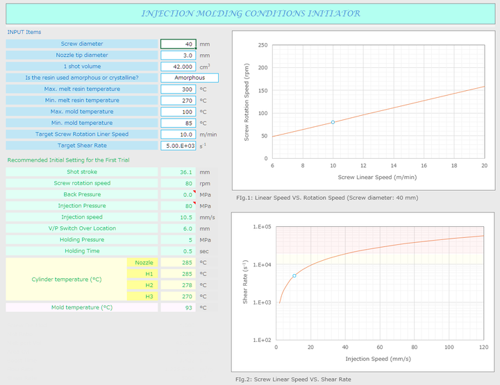
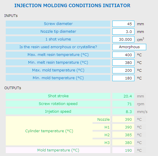
前回の続きです。EXCEL を使いながら、一部の見直しを含めて作ってみると、右図のようになりました。
出力される項目は、
+ 計量値、スクリュー回転数、
+ 背圧、射出圧力、射出速度、
+ V/P 切替え位置、保圧、保圧時間、
シリンダー温度、
+ 金型温度の初期設定値になります。
Continuing from the last episode. When I created the sheet using EXCEL with some modifications, it turned out to look like the image on the right.
The output items which they are recommended for the initial settings are:
+ Shot stroke, Screw rotation speed,
+ Back pressure, Injection pressure,
+ Injection speed, V/P switching position,
+ Holding pressure, Holding pressure time,
+ Cylinder temperature, and Mold temperature.
そしてふたつの図はそれぞれ、スクリュー外周速度と回転数、および射出速度と簡易的に求めたノズル部でのせん断速度をグラフ化したものになります。これであれば初回トライ時の初期設定条件の設定に迷うことはなくなると思います。いかがでしょうか。ご意見やご感想、アドバイスを、" こちら " にインプットいただけないでしょうか。さらに良いシートを目指して、こちらで公開できるように頑張りますので、どうぞよろしくおねがいします。
In addition, the two figures are graphs of "screw peripheral speed VS. rotational speed", and "injection speed VS. simply determined shear speed at the nozzle". If you use this sheet, you won't have to worry about setting the initial settings when you try it for the first time. What do you think? Could you please input your opinions, impressions, and advice "
here " ? I'll do my best to make even better sheets and publish them here, so I appreciate your help.
Structural Analysis 1 (Episode 14: 3D CAD)
さて、今回からは構造解析について触れていきたいと思います。構造解析は、形を持った物体に力や変位などを加えた時の応力や変位、あるいは周波数の応答などを計算する手法で、一般的には有限要素法が多く用いられます。この解析では数値化およびそれを用いて多くの計算が必要となるため、コンピューターが使われます。構造解析の第一歩としては、まず課題となる物体を 3 次元形状でデータ化する必要があります。そして、そこで使われるのが 3D CAD です。もちろん多くのソフトウエアが市販されています。私はかつては Solidworks を使っていました。しかし、企業に属さない今では、とても買うことも維持することもできません。そこで注目したのがオープンソース の FreeCAD です。
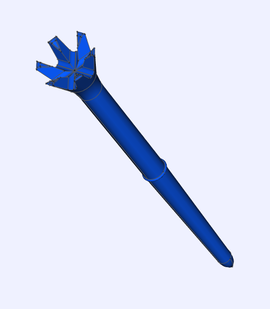
マニュアルはなかったのですが、最初は一本の線を描くのに実は数時間もかかっちゃいました。Solidworks と同じパラメトリック・モデリングなのに細部が微妙に違っていましたので・・・。 正しい手順を知ってしまえば、なんでもなく直ぐに出来る事なのです。 まずは慣れるために添付画像のようなゴルフで使うティーの形を作りました。 FreeCAD でも STL 形式で書き出せると思うのですが、これは 3D プリンタで作れる形状なのでしょうか? 3D プリンターには詳しくないので良くわかりませんが、難しそうです。 少しだけ勉強してみようかな。
Now, from this time episode, I would like to touch on structural analysis. Structural analysis is a method of calculating stress, displacement, or frequency response when force or displacement is applied to a shaped object, and the finite element method (FEM) is generally used. This analysis requires digitization and many calculations using it, so computers are used. The first step in doing that is to convert the target object into data in 3D form. And that's where 3D CAD is used. Of course, there are many software products available on the market. I used to use Solidworks. However, now that I'm not belong to a company, it is impossible to buy or maintain it. That's why I focused on FreeCAD which it is open source software.
When I used it first, there was no manual, it actually took several hours to draw a single line. Although it uses the same parametric modeling as Solidworks, the details were slightly different. Once I'd know the correct procedure, I could have easily got it done. First, to get used to it, I made the shape of a golf tee like the attached image. I think FreeCAD can also export in STL format, but is this a shape that can be created with a 3D printer? I'm not familiar with 3D printers, so I don't really understand, but it seems difficult. I think I'll try studying it a little bit.
Structural Analysis 2 (Episode 15: 3D CAD)
3D プリンターについてはサポートの設置の仕方と除去方法が鍵になりそうですね。これについては少しおいていおくことにして、構造解析のソフトをあたってみました。そしてその中から PrePoMax を使ってみることにしました。これはソルバーに CalculiX を用いた、プリ・ポスト統合型のオープン・ソース・ソフトウエアです。
その精度を簡単に検証するために、平板形状のモデルを作成し、片持ち梁の計算をしてみました。形状は、L: 125 mm x W: 12.5 mm で、肉厚は 2.2 mm。材質の縦弾性係数は 2300 MPa。 これを片端を固定して先端に 0.1 N を集中荷重としてかけた時の最大変形量と発生応力を梁計算してみると、2.56 mm と 1.24 MPa という計算結果となりました。
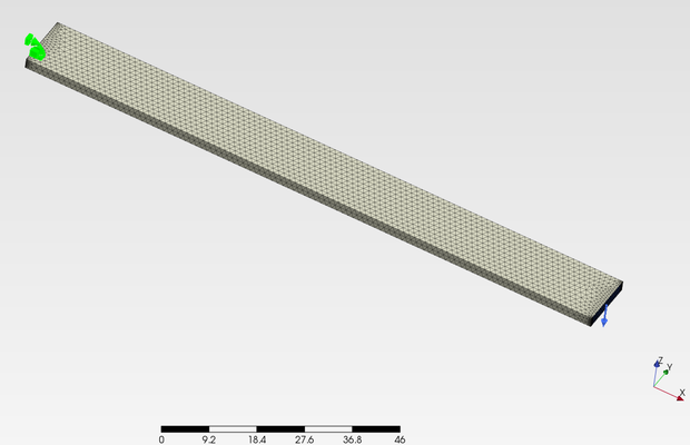
そして同様の形状を FreeCAD でモデリングして PrePoMax を使って解析しました。線形の静解析です。図はその時作成した有限要素モデルです。ちなみに要素数は 10,489 です。また解析時には、ポアソン比を 0.38 としました。
結果は・・・、次回に報告します。
Regarding 3D printers, how to design and remove supports seems to be the key. I decided to leave this for a moment and tried using structural analysis software. Then, I decided to try using PrePoMax. This is a pre-post integrated open-source software that uses CalculiX as a solver.br
In order to easily verify its accuracy, I created a flat plate model and calculated as a cantilever beam. The shape is L: 125 mm x W: 12.5 mm, and the wall thickness is 2.2 mm. The Elastic modulus of the material is 2300 MPa. When one end of this beam was fixed and a concentrated load of 0.1 N was applied to the tip, the maximum deformation and generated stress were calculated as 2.56 mm and 1.24 MPa.
The same shape was then modeled in FreeCAD and analyzed using PrePoMax. I used a linear static analysis. The figure shows the finite element model created at that time.The number of elements is 10,489. In addition, during the analysis, Poisson's ratio was set to 0.38.
I'll report the results.... next time.
Structural Analysis 3 (Episode 16: FEA)
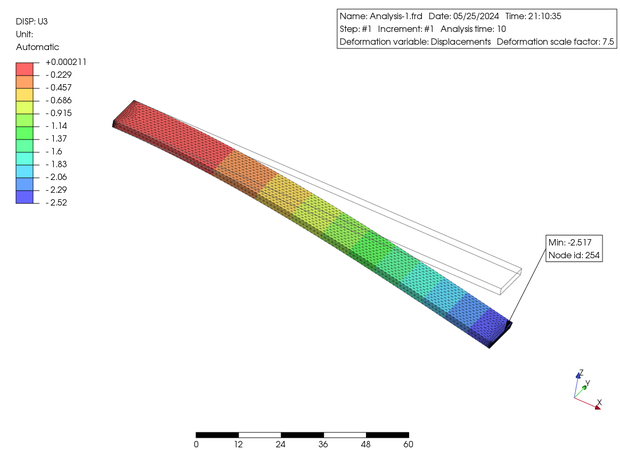
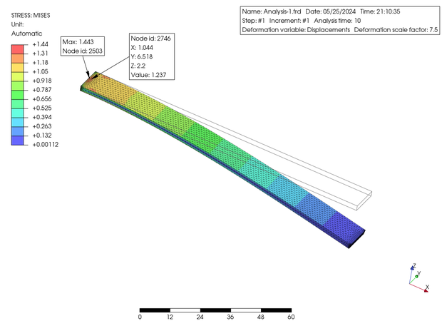
左に示した図は PrePoMax からの結果出力で U3 (Z 軸) 方向の変位と Von-Mises 応力のコンタープロットになります。変位は最大 2.517 mm でした。そして Mises 応力は最大値は 1.443 MPa となっていますが、この点は特異点と判断して最寄りの接点での値を表示させると 1.237 MPa でした。前述の梁計算の結果 (2.56 mm と 1.24 MPa) と比較して、かなり近い値が得られました。この解析においては実用的に問題なく、精度も高いと思われます。いかがでしょうか? ちなみに Solver は CalculiX を用いています。
今回は変位が微小であることが予測できたので、線形解析でしたが、PrePoMax は幾何非線形や接触解析などにも対応しているようですので、次回はもう少し複雑な形状でそれらも試してみたいと思います。
The figures above are contour plots of displacement in the U3 (Z-axis) direction and Von-Mises stress, which are the result output from PrePoMax. The maximum displacement was 2.517 mm. The maximum stress was 1.443 MPa, but if I determine that the point is a singularity and display the value at the nearest node, it is 1.237 MPa. These values are quite close to the results of the beam calculation mentioned above (2.56 mm and 1.24 MPa). I guess that PrePoMax is practically acceptable and appears to be highly accurate from this time results. What do you think? By the way, PrePoMax is using CalculiX as solver.
This time, I predicted that the displacement would be very small, so I used a linear analysis, but PrePoMax seems to also support geometric nonlinearity (NLGeom) and contact analysis, so next time I'd like to try these with a more complex shape.
Structural Analysis 4 (Episode 17: CAD Modeling)
前回、もう少し複雑な形状で・・・と書きましたが、FreeCAD を使ってモデリングを進めていたところ、シェル化がうまく出来ませんでした。また、フルモデルから 1/4 モデルへの切り取りも上手く出来ませんでした。さらに補強リブの設置も専用コマンドも無いようで、とても手間がかかりそうです。ということで、しばらく作業が停止していました。後ほど気づいたのですが、どうやら曲面を一部に用いていると、これらの手順が上手くいかないようです。
Last time, I noted that I would work on a more complicated shape, but when I was using FreeCAD to make the model, I couldn't perform the 'thickness' operation. I also couldn't cut the full shape model into a quarter shape. Furthermore, there doesn't seem to be a dedicated command for installing reinforcing ribs, so it seemed like it would require a lot of work. So I stopped working on it for a while. Later, I realized hat these operations don't seem to work if I used curved surface for solid model.
そこで、他のソフトを探していたところ、" onshape " というに出会いました。これはフルクラウド型のソフトで、インターネット環境とブラウザさえあれば 3D CAD が操作できます。そして、非商用の個人使用であれば、無料でサインアップ出来るようです。
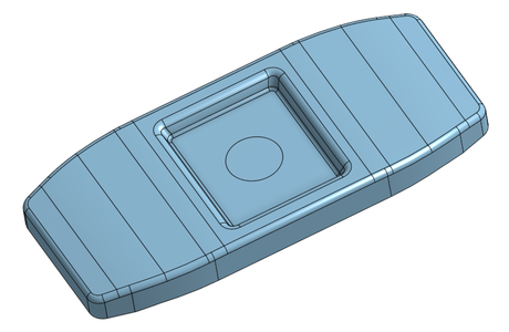
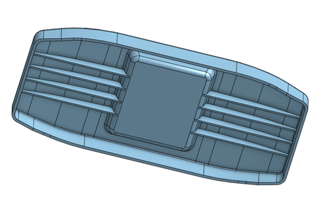
少し使ってみると、先程の FreeCAD での不具合はもちろん無く、至ってスムーズに CAD モデリングが出来ました。使用感も Solidworks に似ているので、それを使っていた私にとっては非常に心地良かったです。上の図は onshape で描いたソリッド・モデルです。これにしてもそれほど複雑なものではありませんが、非常に短時間で制作できました。このモデルを使って、時間は構造解析をしてみたいと思います。
So, I was looking for other software and came across "
onshape ". It is a fully cloud-based software, and user can operate 3D-CAD with just an internet connection and a browser. It seems that we can sign up as free for non-commercial personal use.
Using it for a while, I noticed that there were no issues like those I encountered with FreeCAD, and I was able to complete the modeling with ease. The usability is also similar to Solidworks, so it was very comfortable for me, who had been using it. The images above are a solid model drawn with onshape. Even though, the shape is not particularly complicated, I could to create it in a very short time. I would like to use this model to try structural analysis next.
Structural Analysis 5 (Episode 18: PrePoMax, Simple Loading)
さて今回は、前回作成した形状に荷重をかけて、変形量と最大主応力を求めてみました。使用ソフトは PrePoMax です。あらかじめ onshape で、課題となる形状の 1/4 モデルを再生しておき、STEP 形式でエクスポートしたものを PrePoMax にインポートしました。そして最下面を完全拘束し、中央部の直経 28 mm 円のエリアに 0.3 MPa の面圧をかけた時の中央部の最大変位と中央裏側の発生最大主応力を結果表示させました。またこの時、支持体となる直方体形状のパートも作成しておきました。この直方体にターゲットとなるパートを乗せたときのシミュレーションも、接触解析を用いて行ってみました。それらのコンター図を以下に示します。
Case 1 は幾何線形の解析で、最下面のZ 軸方向を拘束しています。Case 2では Case 1 に対して幾何非線形としています。Case 3 は支持体との間に接触を考慮しています。そして、材料は PrePoMax のライブラリにあった ABS を、また支持体については S180 を使用しました。
This time, a load was applied to the shape created last time, and the deformation and maximum principal stress were calculated. PreProMax software was used. I created the 1/4 model of the target shape using onshape beforehand, then exported it in STEP format and imported it into PrePoMax. I simulated the maximum principal stress and displacement by applying a fully constrained boundary condition to the bottom surface and loading 0.3 MPa at the center of a 28 mm circle. I also created a brick-shaped part to hold it. Contact analysis was also used to perform a simulation when the target part was placed on the brick. The contour plots are shown below.
The bottom surface's Z-axis direction is constrained in Case 1, which is geometrically linear. In comparison to Case 1, Case 2 is geometrically nonlinear. Case 3 was considered contact solution between the plastic and brick part. And The material used for the plastic part was ABS from the PrePoMax library, and S180 for brick support.
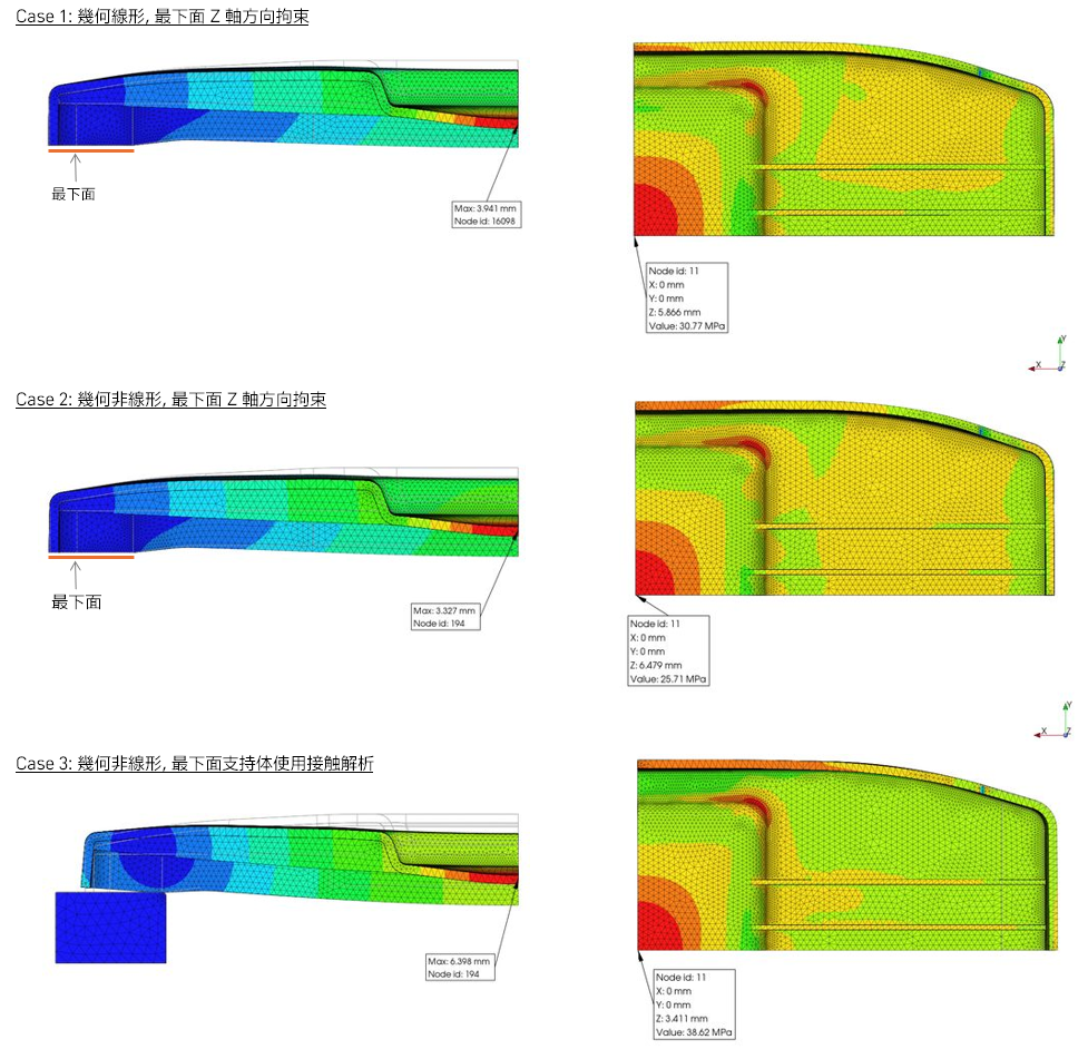
結果をまとめると、
Case 1: 最大変位 = 3.94 mm, 中央部に発生する発生最大主応力 = 30.8 MPa
Case 2: 最大変位 = 3.33 mm, 中央部に発生する発生最大主応力 = 25.7 MPa
Case 3: 最大変位 = 6.40 mm, 中央部に発生する発生最大主応力 = 38.6 MPa
となっています。
いかがでしょうか? なんとなくそれっぽい結果になっていると思います。
The results are summarized as follows:
Case 1: Maximum displacement = 3.94 mm, Maximum principal stress at the center = 30.8 MPa
Case 2: Maximum displacement = 3.33 mm, Maximum principal stress at the center = 25.7 MPa
Case 3: Maximum displacement = 6.40 mm, Maximum principal stress at the center = 38.6 MPa
How do you feel? The outcomes, in my opinion, it somehow seems like that.
Structural Analysis 6 (Episode 19: Gear Tooth Root Stress, #1)
プラスチック歯車の根元に発生する応力を求めてみたいと思います。これに関しては JIS B1759: 「プラスチック円筒歯車の曲げ強さ評価方法」の中に算出方法の記載がありますので、それを基に算出した結果と PrePoMax を使って FEM で得られた結果を比較してみたいと思います。''歯車の諸元としては、モジュール 1、歯数 54、圧力角 20°、歯幅が 10 mm の平歯車とします。''これに噛み合う同諸元の金属歯車に 1 N·m のトルクが掛かった場合を想定してみます。JIS B1759 によれば、歯元の曲げ応力は 6.8 MPa と計算されました (ただし Yf は 1.0、リム厚は 2.0 mm)。
Would like to figure out how much stress is occurred at tooth root of a plastic gear. JIS B1759: "Estimation of tooth bending strength of cylindrical plastic gears" describes the calculation method; thus, I'd like to compare the results derived from it and the results acquired by FEM using PrePoMax. A spur gear with module 1, 54 number of teeth, 20° pressure angle, and 10 mm facewidth is the gear specification. Considering that a metal gear meshing with this has the same specs and is subjected to a torque of 1 N·m. Based on JIS B1759, the bending stress at the tooth root was calculated to be 6.8 MPa (assuming Yf is 1.0, rim thickness is 2.0 mm).
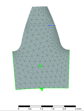
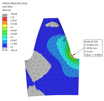
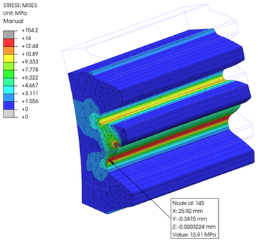
そして、一歯形状を 2D の平面ひずみ状態として要素を作り、PrePoMax で噛み合いピッチ点に 1 N·m を付加させてみましました。その時の有限要素モデルが左の図です。なお、材料は PrePoMax のライブラリから POM を選択しました。そして、その隣に最大主応力の結果コンター図を表示しています。この図によると、応力最大値は 11.3 MPa でした。接点一点に荷重を瞬間的に集中させていることが、結果の応力値を高くしている可能性もあるかもしれません。しかし、ここでの目的は onshape と PrePoMax の使い方を習得する事ですので、得られた値の絶対値に関しては、議論しないこととします。次回は、同じ諸元の歯車を噛み合わせた状態で解析してみたいと思います。
Then, I loaded 1 N·m to the node on the working pitch diameter in PrePoMax using a FEM of a single tooth shape in a 2D plane strain state. On above left is the model with finite elements. I chose POM from the PrePoMax library for the material. The contour plot of the greatest primary stress results is displayed next to it. According to this figure, the maximum stress value was 11.3 MPa. It might be possible that the momentary concentration of the load at one contact point may be responsible for the higher resulting stress value. However, since my goal here is to learn how to use onshape and PrePoMax, I will not be concerned the absolute values obtained. In the next episode, I'm going to analyze the gears with the same specs meshed together.
Structural Analysis 7 (Episode 20: Gear Tooth Root Stress, #2)
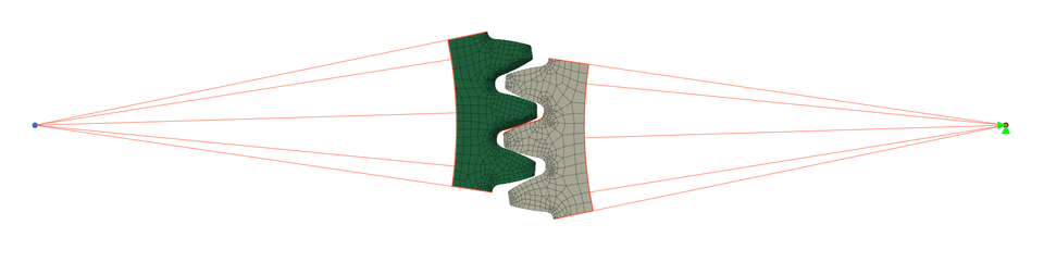
前回に引き続き、今度は同じ諸元の歯車を噛み合わせた状態で有限要素化して解析を行いました。繰り返しになりますが、歯車の諸元としては、モジュール 1、歯数 54、圧力角 20°、歯幅が 10 mm の平歯車で、両歯車とも歯の部分を含めた一部分で切り取っています。中芯間距離は 54.12 mm としています。この数値は前回の JIS 式での計算にも使った値でした。
要素は、これまた前回同様に、平面ひずみを考慮した、厚みを 10 mm とした 2D 要素を用いました。接触部には接触条件を設定しています。さらに両歯車の中心の位置にそれぞれ基準点を作成し、切り取った部分との間を剛性要素で繋いで、金属歯車側の基準点を固定とし、樹脂側の基準点に 1 N·m のトルクを掛けて実行してみました。しかし、結果として計算が収束することはありませんでした。
Continuing from the previous episode, I ran the analysis using FE mesh with the same gears meshed together. Again, the gear specifications were spur gears with a module of 1, 54 teeth, a pressure angle of 20°, and a face width of 10 mm'. and both the pinion and gear were cut out in a portion, including the teeth. The center distance was 54.12 mm. This value was also utilized in the previous calculation based on the JIS formula.
As in the previous analysis, 2D elements with a thickness of 10 mm were used, considering the plane strain. Contact conditions were set at the contact edges. Furthermore, reference points were created at the center of each gear, and rigid elements were used in order to connect the cut-out parts. The reference point on the metal gear side was fixed, and a torque of 1 N·m was applied to the reference point on the resin side. However, the calculation did not converge.
解析ログを見てみると、接触した途端に変形量に異変が生じているような感じがしました。リジッド要素と 2D 要素の組み合わせが、うまくないのかもしれません。ちなみにトルクを加えるのではなく、基準点に微小角度の強制変位を与えてみましたが、このケースも収束しませんでした。このケースではさらに固定している側の基準点に発生する反力を出力したかったのですが、アウトプットされませんでした。というわけで、次回は 3D 要素を使うことに変更してトライしたいと思います。
When I looked at the analysis log, I noticed that something strange was happening to the deformation amount as soon as they made contact. The combination of rigid element and 2D element may not be good. As a side note, instead of adding a torque, I tried giving a small angle of forced displacement to the reference point, but this case did not converge neither. At that time I also wanted to output the reaction force generated at the fixed reference point, but this was not output either. Therefore, next time I will try and change it to using 3D elements.
Structural Analysis 8 (Episode 21: Gear Tooth Root Stress, #3)
今度こそは・・・と、3D 要素を使って要素化を行い、これまでと同様にそれぞれの歯車の中心を基準点として、歯車形状部の接点とを剛性要素でつなぎました。その上で金属歯車側の基準点を固定し、樹脂歯車側の基準点に微小角度の強制変位を与えた時の、金属側基準点に発生する反力を出力させてみると、今回はしっかり出力されました。
This time, I created elements using 3D elements, and just like before, I set the center of each gear as the reference point, and connected between nodes of the gear shapes with rigid elements. I then fixed the reference point on the metal gear side, and forced a small angular displacement to the reference point on the plastic gear side. I then tried to output the reaction force generated at the reference point on the metal side, and this time the output was come correctly.
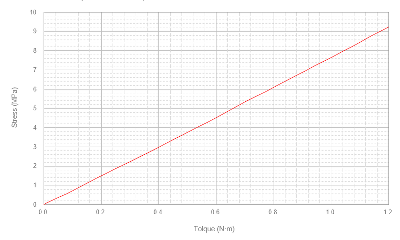
そして、出力された反力と最大のミゼス応力をグラフ化すると下図のようになります。この図から、反力が 1 N·m の時の発生応力は 7.7 MPa でありことが分かります。Episode 19 で JIS に基づいて計算した 6.8 MPa より高い値とはなりましたが、2D 要素で噛み合いピッチ点に 1 N·m 直接負荷したケースよりは低い値となりました。
今回の一連の試みによって、少しずつですが PrePoMax の使い方が分かってきたように気がします。そして、とても興味深い実行結果となりました。
The graph below shows the reaction force and maximum Mises stress output. From this graph, we can see that the occurred stress is 7.7 MPa when the reaction force is 1 N·m. Although this value is higher than the 6.8 MPa calculated based on JIS in
Episode 19, it is lower than the case where 1 N·m was directly loaded to the meshing pitch point with 2D elements.
Through this series of attempts, I feel like I am gradually beginning to understand how to use PrePoMax. And the execution results were very interesting.
Structural Analysis 9 (Episode 22: Snap Fit)
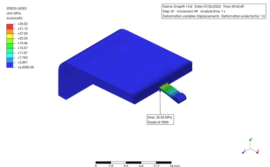
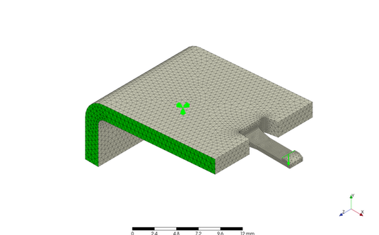
スナップフィットの構造解析を行ってみました。下図は最も単純な形状のスナップフィットです。製品からその部分だけを切り取ってモデル化しています。その切り取った部分を完全な拘束した上で、爪部分を強制変異させます。なお、詳細寸法は省略させていただきます。材料は、PrePoMax のデータにあった ABS をそのまま使いましたが、縦弾性係数は 2,000 MPa でポアソン比は 0.39 となっていました。
Performed a structural analysis of the snap fit form. The figure below has the simplest snap-fit shape. Only that part was removed from the product and modeled. The cut out area is fully constrained, and the hook is force-displaced. Detailed dimensions will be omitted.. The material used was ABS from the PrePoMax data. The modulus of elasticity was 2,000 MPa, and the Poisson's ratio was 0.39.
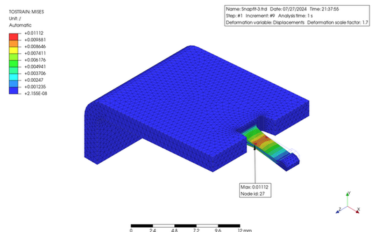
解析結果を見ると、ミゼス応力の最大値は 35 MPa、最大歪は 0.024 でした。使用した ABS 樹脂の PrePoMax の材料データには強度のデータがありませんでしたが、一般的な ABS 樹脂の強度から推定すると、これらの値は、ほぼ降伏点に近いと考えられるため、スナップフィットとしてデザインするには大きすぎると思います。その改善案としてはアームを長くするか、肉厚やたわみ量を減らす事が考えられます。その下の図は、アームの長さを増加することによって、ひずみを低減させた一例になります。なお、肉厚の徐変なども配慮しています。許容応力やひずみに関しては、使用する材料の S-S 曲線から決定する必要があります。ひずみを与える回数なども考慮する必要があります。また、これとは別に、引き抜き強度も考慮する必要もありますね。
The analysis results showed that the maximum Mises stress was 35 MPa, and the maximum strain was 0.024. The PrePoMax material data for the ABS resin used did not include strength data; however, by guessing from the strength of typical ABS resin, these values are likely to be close to the yield point and therefore too large to be designed as a snap fit. Possible solutions include increasing the arm length or reducing the thickness or deflection. The bottom figures show an example of reducing the strain by increasing the arm length. In addition, consideration was given to the gradual change in the thickness. The allowable stress/strain must be determined from the S-S curve of using material. The number of snap times must also be considered. In addition, the pull-out strength must be considered.
~~~ Original Design ~~~

~~~ Modified Idea ~~~

Structural Analysis 10 (Episode 23: Thermal Conductivity Analysis)
今回は ProPoMax を使って熱伝導解析を行ってみました。LED 電球から発せられる光自体は熱くないのですが、LED 素子自体は発熱するため、その熱を放熱する必要があります。これを簡単にシミュレートできるように、次のような解析をすることにしました。
有限要素モデルは、金属製の円形で皿状のプレートに筐体が接続されている、LED 電球をイメージしています。プレートの上には熱源となる LED 素子が置かれるとして、12 箇所の四角形状のエリアを設定して、それらの各面に 35 mW/(mm^2·°C) の熱流束を与えました。そしてこの時、プレートと筐体の接触面には 10 mW/(mm^2·°C) をギッャプ伝導率として与えました。また、筐体の空気との接触面には 0.02 mW/(mm^2·°C) の境膜伝熱係数を設定し、空気の温度は 25°C としました。
筐体の材質は、金属 [熱伝導率: 160 mW/(mm·°C)] と一般的なプラスチック [熱伝導率: 0.2 mW/(mm·°C)] 、そして熱伝導率の高いプラスチック [熱伝導率: 4 mW/(mm·°C)] の 3 種類を想定して、これらの比較をしました。
In this case, I tried to perform a heat conductivity analysis using PrePoMax.
The light emitted from the LED bulb itself is not hot, but the LED element itself generates heat, which must be dissipated. To simulate this roughly, I had done the following analysis.
The finite element model was imaged an LED light bulb, with an enclosure connected to a circular, dish-shaped metal plate made of metal. Assuming that an LED elements are placed on the plate as heat source, 12 rectangular areas were set and a heat flux of 35 mW/(mm^2·°C) was applied to each surface ares. The contact surface between the plate and the enclosure was given a gap conductance of 10 mW/(mm^2·°C). The contact surface between the enclosure and the air was set to a film heat transfer coefficient of 0.02mW/(mm^2·°C), and the air temperature was set to 25°C.
Three kinds of materials were applied to the enclosure: metal [thermal conductivity: 160 mW/(mm-°C)], common plastic [thermal conductivity: 0.2 mW/(mm·°C)], and high thermal conductivity plastic[thermal conductivity: 4 mW/(mm·°C)], and these were compared.
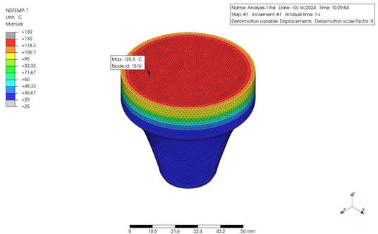
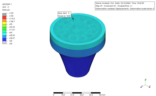
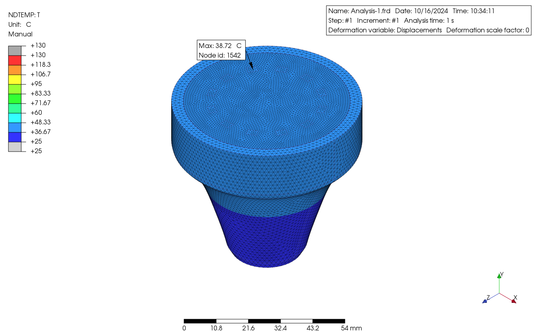
上の図に示したように、熱伝導率の低いプラスチックの筐体を使用した例ではプレートの最高温度が 126°C だったのに対して、熱伝導率の高いプラスチックでは 55°C、金属の筐体を使用すると 39°C と、差がありました。しかし、実際には設定した各係数には誤差が大きく含まれていることが予想され、より正確なシミュレーションを行うためには、実機テストを行った上での各係数の合わせこみが必須となります。さらに、特に熱伝導率を高めたプラスチック材は、充填剤が使用されていることに起因する熱伝導率の異方性 (面内と板厚方向で異なる値となる) や、全体に放射率を考慮していない等の誤差要因もありますので、ここではあくまで PrePoMax の使い方の一例としてのご紹介であることを、ご理解いただきたいと思います。
As shown in the figures above, the maximum plate temperature was 126°C when a plastic encloser with low thermal conductivity was used, whereas it was 55°C when a plastic encloser with high thermal conductivity was used, and 39°C when a metal encloser was used. However, it is expected that the coefficients set in reality contain a large amount of error, and in order to perform a more accurate simulation, it is essential to adjust each coefficients after conducting actual equipment tests. In addition, plastic materials with high thermal conductivity in particular have error factors such as anisotropy of thermal conductivity (different values in the in-plane and plate thickness directions) due to the use of fillers, and not taking into account emissivity overall, so please understand that this is only an example of how to use PrePoMax.
Structural Analysis 11 (Episode 24: Reaction Force Analysis)
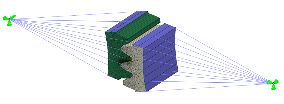
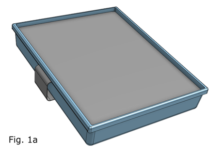
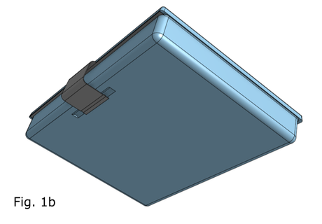
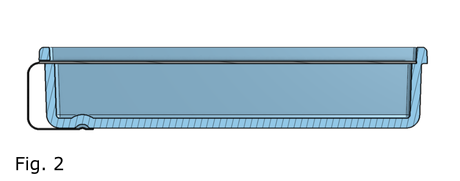
だいぶ間隔があいてしまいましたが、今回も PrePoMax を使って、構造解析をしてみた例をご紹介します。Fig 1a, 1b は、蓋のついた小物入れです。ケースは樹脂製、蓋は金属製としました。蓋はスライドして開けるようになっていて、閉めた時は蓋の出っ張りがケースの溝に嵌って、すぐには開かない構造にしてみました。ただし、制作の容易性については一切考慮していまかんので、ご了承願います。わかりやすいように断面図を Fig 2 に示します。この蓋を開けるためにスライドさせた時に必要な力を探ってみました。
It has been a while since the last post, but this time, I will present another example of structural analysis using PrePoMax. Fig 1a and 1b show a small accessory case with a lid. The case is made of plastic, and the lid is made of metal. The lid can be opened by sliding it, and when closed, the protrusion on the lid fits into a groove in the case, so it will not open immediately. To make it easier to understand, a cross-section is shown in Fig 2. However, please note that I did not consider the ease of production. I tried to determine the force required to slide the lid open
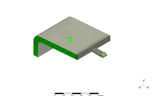
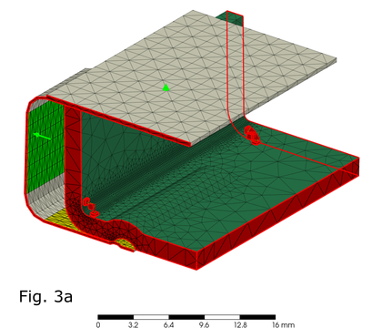
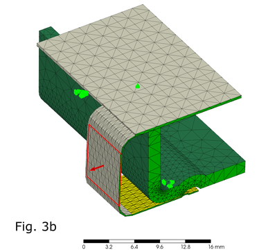
最初は全体モデルで解析しようとしてみたのですが、残念ながら要素数が多すぎて時間がかかり過ぎるため、途中で断念しました。そこで、有限要素は部分的なモデルとして、切断面には対象拘束また強制切断面には完全拘束を設定しました。そして、蓋がスライするガイド部分には、接触要素ではなく適宜に拘束条件を追加した上で、蓋を引っ張る取っ手部分の面に、0.8 mm の強制変位を与えました (Fig. 3a および 3b)。
First, I tried to analyze the entire model; however, unfortunately, there were too many elements and it took too much time; thus, I gave up midway. Therefore, the finite elements were made as a partial model with symmetric constraints and full constraints on the cut surfaces. Then, appropriate boundary conditions were added to the guide surfaces where the lid slides, instead of contact elements, and a forced displacement of 0.8 mm was applied to the surface of the handle part that pulls the lid (Fig. 3a および 3b).
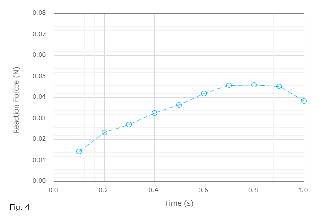
そして完全拘束面の接点の中で最も高い反力を生じた接点における反力を時間とともに出力し、グラフにしたものが Fig. 4 になります。本例でのデザインおよび採用した各パラメーターの値では出力された値自体は小さかったですが、このような手順で蓋を開く際に必要な力を推察できることがわかりました。また、最後に変位のアニメーションも掲載しておきます。
At the node among in the fixed surface that showed the highest reaction force, I outputted the reaction forces , and then plotted the graph shown in Fig. 4. Although the output forces were small for the design of this example and the values of the parameters applied, I understood the method to estimate the force required to open the lid through this procedure. In addition, an animation of the displacement is posted.
Go back to the top of this page.